Asynchronous Replication
Introduced with TintriOS release 2.0, Tintri ReplicateVM extends the snapshot and cloning capabilities of Tintri VMstore to appliances in a single data center or across multiple data centers.
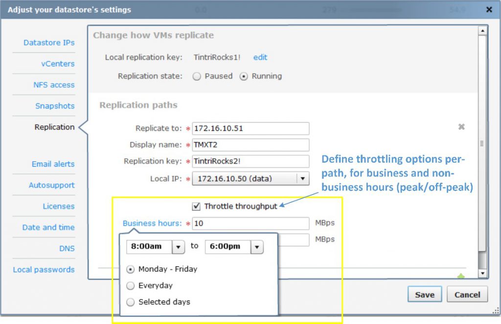
Figure 19. Pointing to the VMstore for the replication path.
Like cloning, ReplicateVM also uses the point-in-time snapshots of a given VM as the measure of replication. For example, a snapshot schedule that creates snapshots every 15 minutes determines what is replicated every 15 minutes. Therefore, for a VM protected with replication, the snapshot schedule and the replication schedule are one and the same.
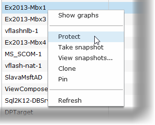
Figure 20. Preparing to snapshot the virtual machine.
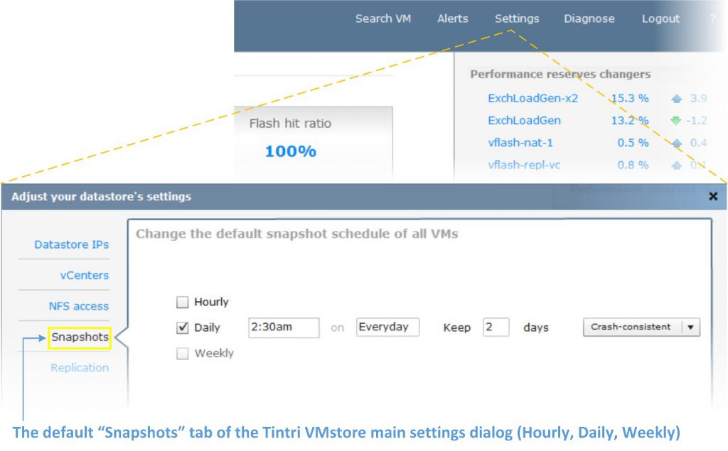
Figure 21. Setting snapshot schedules.
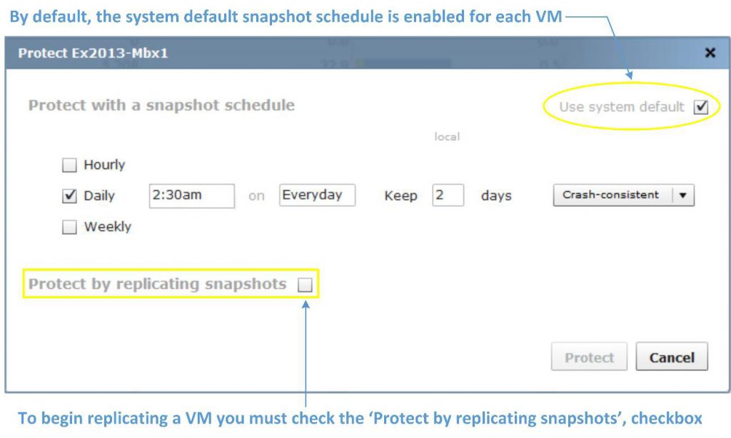
Figure 22. Replicating snapshots.
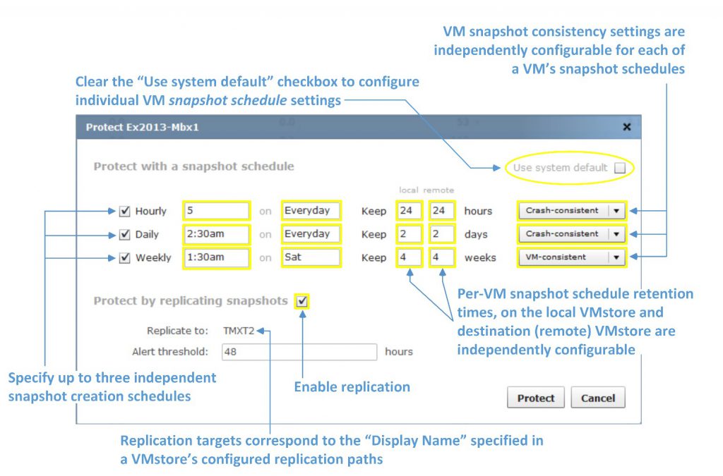
Figure 23. Many options are available for snapshot replication.
Tintri VMstore currently supports 16 paths per system. Setting up replication paths between Tintri VMstore systems is straightforward. On each Tintri VMstore:
- Specify the network path to your destination Tintri VMstore (Figure 19)
- Right-click on each VM and select the “Protect” (snapshot scheduling) options for a VM (Figure 20)
- Specify up to 3 snapshot schedules for each individual VM (Figure 21)
- Check the “Protect by replicating snapshots” checkbox (Figures 22, 23)
In addition to specifying the host name and IP address for a path, Tintri VMstore requires administratively-defined replication keys when setting up paths. You can create and use more cryptic looking keys, but entering keys that are easier to remember and type are easier. Each administrator will decide what works best for their organization.
In addition to specifying the local and destination network paths between Tintri VMstore devices, ReplicateVM path specifications include options to throttle, or limit the maximum amount of snapshot data transferred in megabytes-per-second (MBps), over each defined path.
Throttling throughput allows administrators to regulate and predictably manage the bandwidth utilization used by replication during business and non-business hours. This is particularly beneficial when replicating data over fixed wide-area network (WAN) leased lines between data centers in different locations, and in different time zones.
The system default snapshot schedule does not determine per-VM replication with ReplicateVM. However, when you select a VM for replication, you can “inherit” or use the system default snapshot schedule (Figure 21) for replication, or create an individual schedule for each VM (Figure 22).
To configure a default schedule for all VMs on the system, click the “Settings” menu on Tintri VMstore, and then select the “Snapshots” tab (Figure 21).
Configuring per-VM replication is a matter of selecting a VM and instructing Tintri VMstore to protect it by creating snapshots of the VM according to the desired (hourly, daily, weekly) snapshot schedules, and then replicating those snapshots to a destination Tintri VMstore.
The “Protect” menu opens the protection settings for the selected VM. Note in Figure 22 that the “Use system default” checkbox is initially “checked,” and the schedule matches the system default schedule.
Once a given VM is protected, and the “Protect by replicating snapshots” option is checked, Tintri VMstore will begin transporting a VM’s individual deduplicated and compressed snapshots.
Each VM is configurable with its own snapshot and replication settings. Figure 23 describes the additional options available for each individual VM when you clear the “Use system default” checkbox.
The options in Figure 23 are applicable to any VM on Tintri VMstore. Notably absent references to arcane and complex storage-related tasks are not omissions. Tintri VMstore keeps the focus on the VMs and their applications and services.
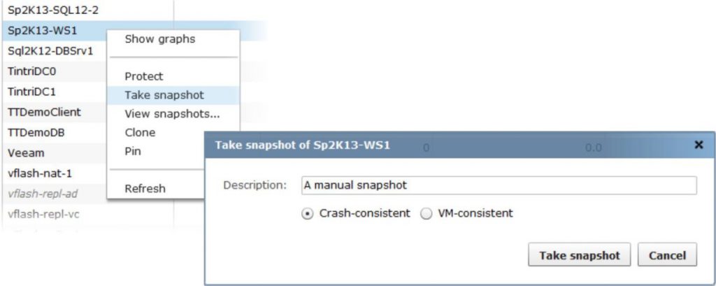
Figure 24. Taking a manual snapshot of a virtual machine.
New snapshots trigger ReplicateVM updates. Therefore, a snapshot created via one of Tintri VMstore’s per-VM schedules, or because of an administrative action (Figure 24), will initiate a ReplicateVM update to a VM’s destination VMstore.
For a VM protected by snapshots and ReplicateVM, each replication update is deduplicated and compressed, to provide optimal performance and fast VMstore-to-VMstore transfer times with maximum network efficiency.
Known for its intuitive UI and integrated per-VM graphing capabilities, Tintri VMstore adds new monitoring and graphs for ReplicateVM that allow administrators to monitor replication performance on a per-VM basis.
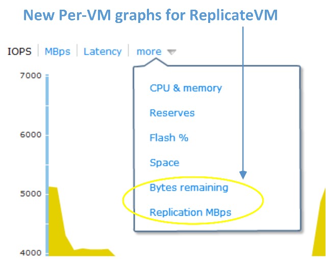
Figure 25. A ReplicateVM graph, accessed via a virtual machine’s dropdown.
A VM’s ReplicateVM graphs can be accessed easily from the Tintri UI by selecting the “more” dropdown list for the VM (Figure 25). ReplicateVM graphs are viewable on both the originating (source) and remote (destination) Tintri VMstore systems for each VM. The progress and throughput of a VM, as well as its overall replication status, is clearly visible and easy to see at-a-glance.
In Figure 26, the logical throughput represents the full size of the data if it were not deduplicated and compressed. The network throughout is the actual amount of data (measured in MBps) being actively transferred. Deduplication and compression are natural attributes of ReplicateVM.
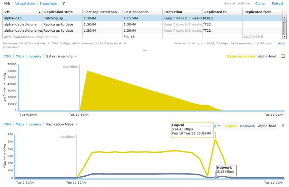
Figure 26. Data size of a virtual machine before deduplication and compression.
Tip: Remember that for each path configured between your Tintri VMstore appliances, configurable throttle values determine the upper limit or replication throughput ceiling (measured in MBps) for a given path during peak and non-peak business hours.
In addition to the cloning options mentioned in the “VM Cloning with Tintri VMstore” section of this paper, ReplicateVM extends the cloning power of Tintri VMstore and provides an array of new and flexible options:
- You can replicate VMs from Tintri VMstore to VMstore in one-to-one, and many-to-one topologies, bi-directionally (in both directions)
- Cloning for restore or deployment operations, is supported locally (on the originating end of VM’s replication path), and remotely (on the destination VMstore), to which a VM’s snapshots are being replicated (i.e., via remote cloning)
For VMs protected by ReplicateVM, remote cloning (Figure 27) allows an administrator to create new VMs from snapshots on the remote or destination end of a ReplicateVM configuration. On the remote VMstore, the virtualization administrator simply browses the Tintri VMstore using the datastore browser in the vSphere client for example, and then adds the new VM to vCenter inventory. Remote cloning is a powerful remote management feature with many possible applications.
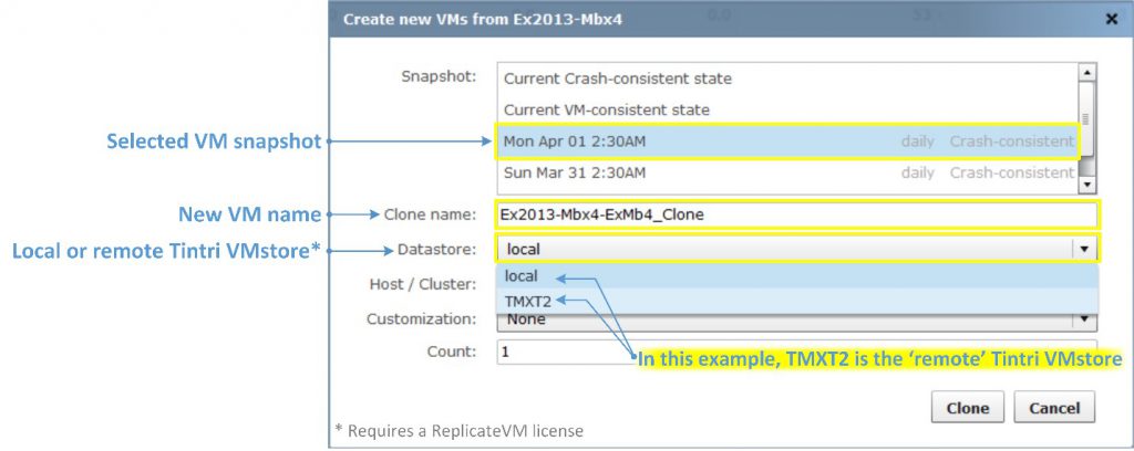
Figure 27. Remote cloning is powerful.
ReplicateVM can be incredibly useful for many applications. The list below is a sample of the applications used by Tintri customers, including applications tested and supported by Tintri VMstore with ReplicateVM.
- VMware Horizon View (VDI)
- Citrix XenDesktop (VDI)
- Microsoft SQL Server 2005 (including database mirroring for HA)
- Microsoft SQL Server 2008/R2 (including database mirroring for HA)
- Microsoft SQL Server 2012 (including Always On Availability Groups for HA)
- Microsoft Exchange Server 2010 (including Database Availability Groups for HA)
- Microsoft Exchange Server 2013 (including Database Availability Groups for HA)
- SAP on Unix and Windows
- Engineering and Geo-physical applications
- Test, Development and QA
- Transactional Financial Applications
- Private Cloud and Hosting Provider implementations
- Business Intelligence and Reporting Applications
ReplicateVM is particularly powerful when it comes to replicating important, mission-critical data sets and assets essential to the operations of an organization. This includes, but is not limited to, protecting the core VM and application images used in server and desktop virtualization environments, and replicating the snapshots of those applications and images across multiple systems in geographically dispersed data centers.
Advantages of Per-VM Snapshots
For the purposes of this document, assume that software-based snapshots are implemented by a hypervisor server, such as vSphere ESXi.
Hardware-based snapshots are features implemented in storage systems with capabilities that extend beyond the basic functionality of Direct Attached Storage (DAS) or “Just a Bunch of Disks” (JBOD) storage.
Software-based snapshots such as vSphere’s native snapshots are typically free and exceedingly easy to use. Software snapshots are also VM-specific.
VMware vSphere ESX/ESXi snapshots implement a series of related virtual hard disk files, or “snapshot chains,” to manage and track a VM’s snapshots. Unfortunately, the practical applications of software snapshots are limited due to the extraordinary and widespread IO activity associated with a VM’s disk chain. The penalties even on fast (i.e. flash/SSD) drives can be serious and costly, given the amount of flash/SSD storage space consumed by the disk chain’s snapshot files.
VMware’s best practices recommend no more than three (software) snapshots at a time for a VM, and you should avoid using and retaining them past 24-72 hours to avoid significant performance complications.
The common attribute that all storage-based snapshots share is that they allow hypervisor host servers to delegate the heavy lifting of creating and managing the snapshots to the storage, freeing host server resources.
While hardware-based snapshots are much faster than software-based snapshots, they are not necessarily easier to use. Traditionally structured shared storage systems, even those that employ flash/SDD drives, can simulate “per-VM” snapshots with specialized software or plugins. Unfortunately, the deployment and management complexities, and the limitations of the underlying hardware, are unavoidable.
Tintri VMstore is the only storage appliance that actually creates snapshots of VMs, rather than creating snapshots of arbitrary storage configurations where a VM’s files happen to be located. There is a stark contrast between these two approaches. The entire lifecycle, from the acquisition and deployment costs, to the manageability and TCO of a virtualization storage platform, necessitates a solid understanding of how these choices affect your organization.
SRM Integration for Comprehensive DR
VMware vCenter Site Recovery Manager (SRM) is a DR solution that provides automated orchestration and non-disruptive testing of centralized recovery plans for all virtualized applications (see more at: https://www.vmware.com/products/site-recovery-manager.)
SRM 5.8 brings additional enhancements for managing DR workflows. The most visible change is that SRM 5.8 is fully integrated as a plug-in with the vSphere Web Client. In addition to not having to use two different interfaces to manage virtual environments, improvements were also made to a few workflows, making it easier and simpler to map arrays, networks, folders, etc. without manual intervention.
This section will walk you through the process of setting up SRM 5.8 on Tintri VMstore 3.1 and provide best practice guidelines to implement a DR solution that is as unobtrusive as possible in day to day (normal) operations, but still provides the RPO (Recovery Point Objective) and RTO (Recovery Time Objective) needed for your business.
This document assumes you are working with a fully configured virtual infrastructure. It also assumes that, in case you are leveraging Microsoft Active Directory (AD) for authentication and policy management and enforcement, that there already is a non-SRM-based AD DR plan in place (i.e., leveraging AD’s native replication) as per Microsoft Best Practices. AD should not be replicated using storage replication technology, as it could potentially cause a USN rollback scenario.
Using VMware SRM with Tintri VMstore
VMware Site Recovery Manager (SRM), combined with Tintri VMstore, shields users from having to manage many of the steps required for traditional recovery. Tintri ReplicateVM provides the ability to configure replication at the VM level (see Figure 28).
Setting up a recovery plan can be done in a matter of minutes, instead of weeks. Ongoing DR provisioning to new VMs can be driven through predefined policies. Actual execution of testing, recovery and migration workflows is fully automated, to eliminate operational complexity.
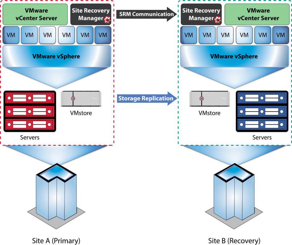
Figure 28. Architectural overview of VMware’s Site Recovery Manager and Tintri VMstore replication for disaster recovery.
Tintri ReplicateVM provides extremely WAN-efficient array-based replication between Tintri VMstores. Tintri’s Storage Replication Adapter (SRA) leverages the easy management and WAN-efficient replication capabilities of Tintri OS to provide SRM-integrated DR workflows, resulting in an extraordinarily simple and quick setup, followed by minimal replication traffic between VMstores. This saves bandwidth and time, lowering TCO. The performance impact on each VMstore is also minimal, enabling an unobtrusive DR strategy with incredibly low TCO.
The list below includes the recommended best practices in this document. For additional information, click the text on any of the recommendations to jump to the section that corresponds to each recommendation.
DO: Use a Microsoft SQL Server database when deploying SRM, rather than an embedded PostgreSQL database.
DO: Install the same version of SRM Server and vCenter Server on both sites (protected and recovery).
DON’T: Use a Tintri VMstore as a placeholder datastore. Use either local hard drives or non-Tintri shared storage.
DO: Make sure you have a ReplicateVM license for your Tintri VMstores.
DO: Try VM-consistent first in a test environment, with copies of the production applications, and testing if the impact is acceptable or not.
DO: Create a Service Group for each SRM Array Manager Pair – i.e., the pair of Protected and Recovery VMstores – that you plan on creating in SRM. There is a 1:1 mapping between Tintri Service Groups and SRM Array Manager Pairs.
DON’T: Try and add a pair of array managers before you create the corresponding Service Group in the primary’s VMstore. The array manager pair creation in SRM will fail if there isn’t a corresponding Service Group already created via the Tintri GUI.
DON’T Run a Recovery Plan for testing; use the Test Recovery Plan feature for testing.
SRM is supported by any edition of vSphere, except vSphere Essentials.
vSphere licenses are required for all servers on which vSphere is installed, whether that host is at a protected site or a recovery site, and whether a server is running or powered down at the recovery site. SRM requires at least one licensed vSphere server at both the protected site and the recovery site.
SRM is supported with vCenter Server for Essentials, vCenter Server Foundation and vCenter Server Standard.
SRM requires two active and licensed vCenter Server instances, one at each site (protected and recovery).
Note: The shared recovery sites feature in SRM enables multiple protected sites with multiple vCenter Server instances to be recovered at a site with a single vCenter Server instance. (The multiple instances of SRM running at the shared recovery site are registered with the same single instance of vCenter Server at the shared recovery site, so you do not need multiple vCenter Server instances at the shared recovery site).
The latest version of SRM can be purchased either as a standalone product or as part of VMware vCloud Suite Enterprise Edition. As a standalone product, SRM is available in two editions, Standard and Enterprise, which can only be purchased on a “per -VM” licensing model. SRM Enterprise edition can also be purchased as part of vCloud Suite Enterprise edition. In this case, SRM is purchased on a “per -processor” licensing model.
SRM Enterprise provides enterprise-level protection to all virtualized applications with no licensing restriction on the number of VMs that can be protected. SRM Standard is designed for smaller environments and limited to 75 protected VMs per physical site and per SRM instance.
Only VMs protected by SRM require SRM licensing. There are two scenarios to consider:
- Uni-directional protection. SRM is configured only to fail over VMs from site A to the site B. In this case, licenses are required only for the protected VMs at protected site A.
- Bi-directional SRM is configured to fail over VMs from site A to site B at the same time that it is configured to fail over to a different set of VMs from site B to site A. In this case, SRM licenses must be purchased for the protected VMs at both sites. Licenses are required for all protected VMs, even if they are powered off.
To fail back from site B to site A (after failover from site A to site B), SRM licenses are required for the “re-protected” VMs at site B. The “per -VM” licenses originally used at site A can be used at site B for this purpose, as long as the licenses are no longer in use at site A.
If SRM is being licensed “per processor” through the vCloud Suite Enterprise at site A, and VMs are failed over to a site B that originally licensed with vSphere only, the vCloud Suite licenses can be transferred to site B in order to “re-protect” and fail back the VMs.
Refer to VMware vCenter SRM 5.8 FAQ for more information.
You must install a SRM Server instance at the protected site and also at the recovery site.
Furthermore, it is recommended that you use (and license) a Microsoft SQL Server database, rather than the embedded PostgreSQL database. SRM 5.8 supports SQL Server 2005, 2008, 2012 and 2014 in almost all its incarnations (including Express, Standard and Enterprise, 32-bit and 64-bit). Check http://partnerweb.vmware.com/comp_guide2/sim/interop_matrix.php for details.
SRM Server can run on the same Windows host operating systems as vCenter Server. For SRM Server 5.8 and vCenter Server 5.5 U2, that includes Windows Server 2008, Windows Server 2008 R2, Windows Server 2012 and Windows Server 2012 R2.
You must install the same version of SRM Server and vCenter Server on both sites. You cannot mix SRM or vCenter Server versions across sites.
For environments with a small number of VMs, you can run SRM Server and vCenter Server on the same system. For environments that approach the maximum limits of Site Recovery Manager (as per http://kb.vmware.com/kb/2081158) and vCenter Server, install SRM Server on a system different from the system on which vCenter Server is installed. If SRM Server and vCenter Server are installed on the same system, administrative tasks might become more difficult to perform in large environments.
If you are using the vCenter Appliance, you will need to install your SRM Servers in a different system than vCenter.
Therefore, at a minimum you will need two Windows 2008/2012 server licenses (one for each site, each running SRM Server and SQL Server and potentially vCenter if no appliance is being used and the environment is small enough), but you may need as many as six, if you install vCenter, SRM and SQL in separate servers in each site.
SRM support is included with the ReplicateVM license. VMstore systems deployed at both the protected site and at the recovery site must be licensed for ReplicateVM.
The system on which you install vCenter SRM must meet specific (virtual) hardware requirements, as shown in Figure 29.
Requirements for Installing SRM
| Component | Requirement |
|---|---|
| Processor | 2.0GHz or higher Intel or AMD x86 processor |
| Memory | 2 GB minimum. You might require more memory if you use the embedded database as the content of the database grows. |
| Disk Storage | 5 GB minimum. If you install Site Recovery Manager on a different drive than the C: drive the Site Recovery Manager installer still requires at least 1 GB of free space on the C: drive. This space is required for extracting and caching the installation package. You might require more disk storage if you use the embedded database as the content of the database grows. |
| Networking | 1 Gigabit recommended for communication between Site Recovery Manager sites. Use a trusted network for the management of ESXi hosts. |
Figure 29. Requirements for installing Site Recovery Manager.
For information about supported platforms and databases, see the Compatibility Matrixes for vCenter SRM 5.8 at Compatibility Matrixes for vCenter Site Recovery Manager 5.8.
SRM Server instances use several network ports to communicate with each other, with client plug-ins, and with vCenter Server. If any of these ports are in use by other applications or are blocked on your network, you must reconfigure SRM to use different ports.
SRM uses default network ports for intra-site communication between hosts at a single site, and inter-site communication between hosts at the protected and recovery sites. You can change these defaults when you install SRM. Beyond these standard ports, you must also (continue to) meet the VMstore’s network requirements.
You can change the network ports from the defaults when you first install SRM. You cannot change the network ports after you have installed SRM.
For a list of all the ports that must be open for SRM, see http://kb.vmware.com/kb/2081159.
For a refresher on the list of all the ports that must be open for the Tintri VMstore, please consult the Tintri VMstore System Administration Manual.
For the list of default ports that all VMware products use, see http://kb.vmware.com/kb/1012382.
Each SRM server can support a certain number of protected VMs, protection groups, datastore groups, recovery plans, and concurrent recoveries.
For details about the operational limits of SRM 5.8 see http://kb.vmware.com/kb/2081158.
For reliability, performance and scalability, it’s strongly recommended to use a Microsoft SQL Server (2005/2008/2012/2014) database instead of the built-in PostgreSQL database. When you create a Microsoft SQL Server database, you must configure it correctly to support SRM.
This section provides the requirements for a SQL Server database for use with SRM. Consult the SQL Server documentation for specific instructions on creating a SQL Server database.
- Database user account:
- If you use Integrated Windows Authentication to connect to SQL Server, and SQL Server runs on the same machine as SRM Server, use the local service account (that has administrative privileges on the SRM Server machine). Use the same account when you install SRM Server. When the SRM installer detects an SQL Server data source name (DSN) that uses Integrated Windows Authentication, it configures SRM Server to run under the same account used for the installer, to guarantee that SRM can connect to the database.
- If you use Integrated Windows Authentication to connect to SQL Server and SQL Server runs on a different machine from SRM Server, use a domain account with administrative privileges on the SRM Server machine. Use the same account, or an account with the same privileges, when you install SRM Server. When the SRM installer detects an SQL Server data source name (DSN) that uses Integrated Windows Authentication, it configures SRM Server to run under the same account used for the installer, to guarantee that SRM can connect to the database.
- Note: this doesn’t always work flawlessly due to problems in the SRM Installer. If it fails, it will do so late in the install with a “retry / fail and back out” error message. If it does so, you can work around the issue by going to the SRM service configuration, changing it to be the correct user (it will incorrectly have set it to local service), and then start the service and hit retry. It should then succeed.
- If you use SQL authentication, you can run the SRM service under the Windows Local System account, even if SQL Server is running on a different machine to SRM Server. The SRM installer configures the SRM service to run under the Windows Local System account by default.
- Make sure that the SRM database user account has the “administer bulk operations”, “connect”, and “create table”
- Database schema:
- The SRM database schema must have the same name as the database user account.
- The SRM database user must be the owner of the SRM database schema.
- The SRM database schema must be the default schema for the SRM database user.
- The SRM database must be the default database for all SQL connections that SRM makes. You can set the default database either in the user account configuration in SQL Server or in the DSN.
- Map the database user account to the database login.
SRM can also support Oracle Server instead of Microsoft SQL Server. Specifically, Oracle 11g Release 2 and 12C are supported. Note, however, that Oracle was not tested during the writing of this best practices guide (only SQL Server was tested). When you create an Oracle Server database, you must configure it correctly to support SRM.
Create and configure an Oracle Server database for SRM via the tools that Oracle Server provides.
This information provides the general steps to configure an Oracle Server database for SRM. For instructions on how to perform the relevant steps, see the Oracle documentation.
- When creating the database instance, specify UTF-8 encoding
- Grant the SRM database user account the connect, resource, create session privileges and permissions
For a typical VMware SRM + Tintri VMstore deployment, you will need two Tintri VMstores: one in the protected site and the other in the recovery site.
The requirements for these VMstores:
- Both VMstores must to be running Tintri OS 3.1 or later
- Each VMstore needs to have a ReplicateVM license installed
- Each VMstore needs to have its respective/local (protected or recovery) vCenter Server configured as a hypervisor manager (in Settings àHypervisor managers).
This section provides information on configuring VMware SRM and the Tintri VMstore. It is assumed that you have met the prerequisites from the previous section, including:
- Have vSphere servers in both sites with the necessary licenses.
- Have fully-configured vCenter Servers in both sites managing all applicable vSphere servers, with the necessary licenses (OS and application).
- The 5.8 release of SRM requires the vSphere Web Client. For information about compatibility between vCenter Server and SRM versions, see vCenter Server Requirements in the Compatibility Matrixes for vCenter Site Recovery Manager 8 at https://www.vmware.com/support/srm/srm-compat- matrix-5-8.html.
- Have fully-licensed SQL Server database servers up and running in both sites.
- Each site can access any necessary AD servers, not protected by SRM, even in case one of the sites goes down in case of disaster (by leveraging AD native replication).
- Have the necessary SRM licenses (permanent or evaluation) and Tintri ReplicateVM licenses.
You must provide SRM with a system database source name (DSN) for a 64-bit open database connectivity (ODBC) connector in the Windows host you chose to install SRM Server on. The ODBC connector allows SRM to connect to the SRM database.
You can create the ODBC system DSN before you run the SRM installer by running Odbcad32.exe, the 64-bit Windows ODBC Administrator tool.
Alternatively, you can create an ODBC system DSN by running the Windows ODBC Administrator tool during the SRM installation process.
Note : If you use the embedded SRM database, the SRM installer creates the ODBC system DSN according to the information provided during installation. If you uninstall the embedded database, the uninstaller does not remove the DSN for the embedded database. The DSN remains available for use with a future reinstallation of the embedded database.
Here’s how to create the database instance to connect from SRM.
- Double-click the Odbcad32.exe file at C:\Windows\System32 to open the 64-bit ODBC Administrator
(Important: Do not confuse the 64-bit Windows ODBC Administrator tool with the 32-bit ODBC Administrator tool located in C:\Windows\SysWoW64. Do not use the 32-bit ODBC Administrator tool.)
- Click the System DSN tab and click Add.
- Select the appropriate ODBC driver for your database software and click Finish.
- SQL Server:
- Select SQL Server Native Client 10.0, SQL Server Native Client 11.0, or ODBC Driver 11 for SQL Server.
- Note: You may need to install the SQL Server Native Client from the SQL Server distribution ISO in case it’s not already installed in the Windows Host.
- Create an SQL Server data source for the
- Select SQL Server Native Client 10.0, SQL Server Native Client 11.0, or ODBC Driver 11 for SQL Server.
- Oracle Server:
- Select Microsoft ODBC for Oracle.
- Create an Oracle Server data source for the
- SQL Server:
- Click Test Data Source to test the connection and click OK if the test If the test does not succeed, check the configuration information and try again.
- Click OK to exit the Windows ODBC Administrator
The ODBC driver for your database is ready to use.
The SRM pre-installation checklist:
- Download the SRM installation file to a folder on the machine on which to install SRM.
- Verify that no reboot is pending on the Windows machine on which to install SRM Verify that no other installation is running, including the silent installation of Windows updates. Pending reboots or running installations can cause the installation of SRM Server or the embedded SRM database to fail.
- The user account that you use to install and run SRM must be a member of the local Administrators group. You can configure the SRM service to run under a specified user account. This account can be a local user or a domain user that is a member of the Administrators group on the machine on which you are installing
- If you are using certificate-based authentication, you must obtain the appropriate certificate You must use the same type of authentication on both sites. See SRM Authentication and Requirements When Using Trusted SSL Certificates with SRM.
- If you are using certificate-based authentication, provide the certificate for the remote site to the vSphere Web Client service on each
- Verify that you have the following information:
- The fully qualified domain name (FQDN) or IP address of the site’s vCenter Server instance. The server must be running and accessible during SRM installation. You must use the address format that you use to connect SRM to vCenter Server when you later pair the SRM sites. Using FQDNs is preferred, but if that is not universally possible, use IP addresses for all
- The user name and password of the vCenter Server administrator
- A user name and password for the SRM database, if you are not using the embedded
- If you use an SQL Server database with Integrated Windows Authentication as the SRM database, you must use the same user account or an account with the same privileges when you install SRM Server used when you created the Integrated Windows Authentication data source name (DSN) for SQL
The steps to install SRM Server are outlined here:
http://pubs.vmware.com/srm-58/topic/com.vmware.srm.install_config.doc/GUID-723EAC1B-AC21-4CAA- 9867-627CA8CB680A.html
After installing each SRM Server (in each site), you will need to also install the Tintri SRA in each site.
The Tintri SRA for VMware SRM can be downloaded from https://support.tintri.com/download/. The installation instructions for the SRA are also available from the same site, in the corresponding release notes.
Before you can use SRM, you must connect the SRM Server instances on the protected and recovery sites. The sites must authenticate with each other. This is known as site pairing.
Steps are outlined here:
http://pubs.vmware.com/srm-58/topic/com.vmware.srm.install_config.doc/GUID-8C233913-6C62-4068- BDD0-49B35D796868.html
After that is completed, the vSphere Web Client should look like Figure 30.
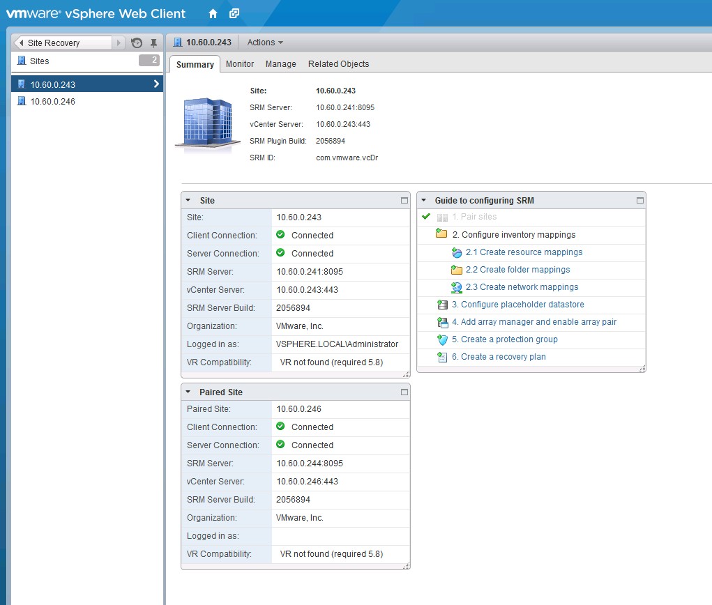
Figure 30. The summary tab after SRM site pairing.
SRM Server requires a license key to operate. Install an SRM license key as soon as possible after you install SRM. Follow the steps outlined here:
http://pubs.vmware.com/srm-58/topic/com.vmware.srm.install_config.doc/GUID-BA06E6CB-C937-4629- A38A-D0342CCC21CA.html
The next step is to configure inventory mappings.
You must create inventory mappings so that SRM can create placeholder VMs.
Inventory mappings provide a convenient way to specify how SRM maps VM resources at the protected site to resources at the recovery site. SRM applies these mappings to all members of a protection group when you create the group. You can reapply mappings whenever necessary; for example, when you add new members to a group.
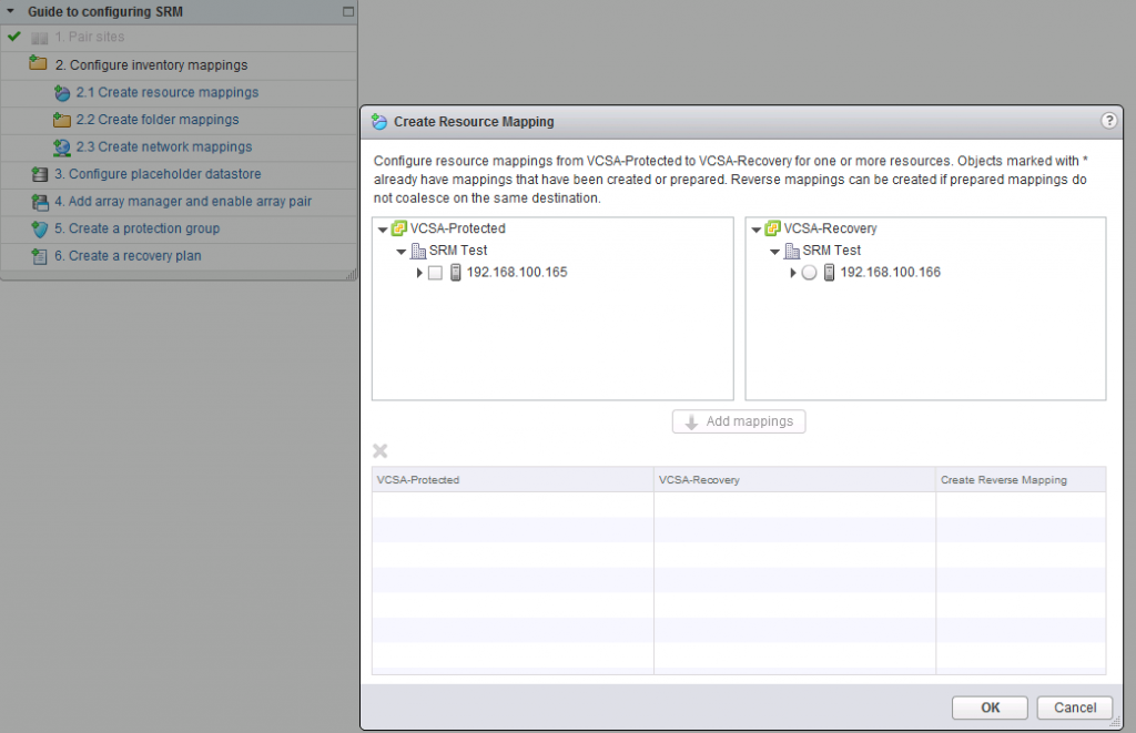
Figure 31. Accessing the configure inventory mappings wizard.
This is done in three steps: create resource mappings (Figure 33), create folder mappings (Figure 32) and create network mappings (Figure 34). Each step can be accessed by clicking the respective link in the “Guide to Configuring SRM” as shown in Figure 31 (accessible by going to Site Recovery –> Sites –> <Protected Site> –> Summary in the vSphere Web Client).
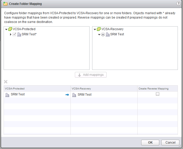
Figure 32. Creating the folder mapping.
In this step, you simply select the resources (e.g. a vSphere server) you want to map in the protected site (in the left pane), and then the equivalent resource in the recovery site (i.e., a different vSphere server located in the recovery site).
This step allows you to map the virtual networks in the protected site to their equivalents in the recovery site.
The next step is to set placeholder datastores for each site (Figure 35). Note that these datastores do not need to be shared or replicated. They are used to keep the .vmx files (not the .vmdk files) on the site that is inactive (recovery site when everything is OK, and the protected site after a failure). In this case, it is a local hard drive in each site.
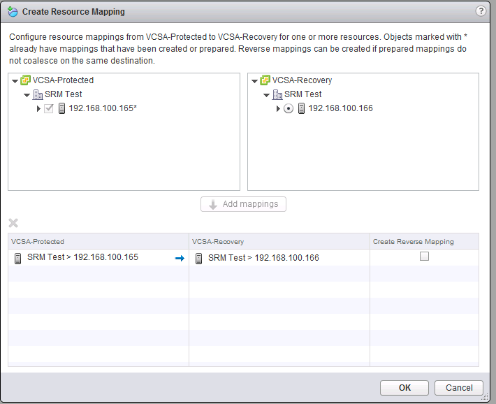
Figure 33. Creating resource mapping.
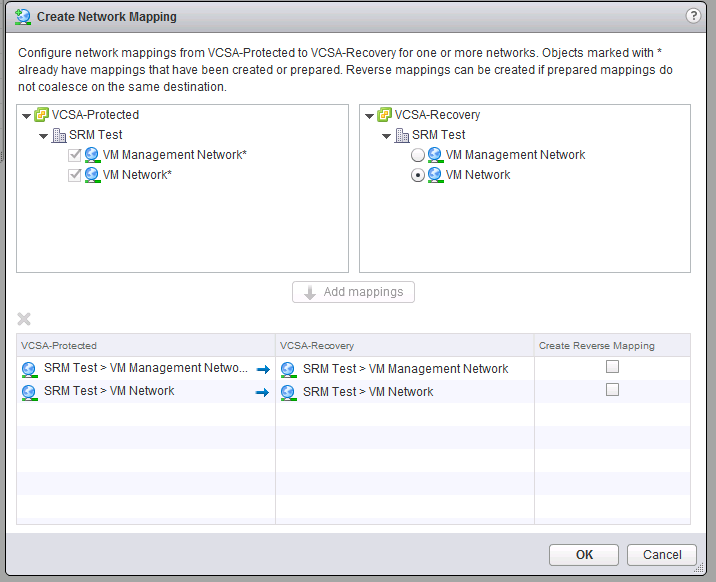
Figure 34. Creating the network mapping.
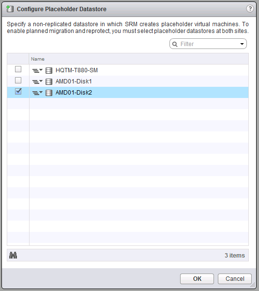
Figure 35. Configuring the placeholder datastore.
Now it’s time for the configuration steps that involve the pair of VMstores you are going to be using.
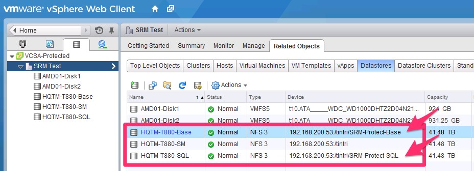
Figure 36. Moving virtual machines into datastores.
- Each VMstore needs to be configured and mounted in each respective vSphere/vCenter as a datastore: one datastore for each group of VMs to be protected (there will be a mapping between SRM protection groups and datastores/mount points on the VMstores).
- For SRM, you cannot use the VMstore’s default /tintri folder. You will need to create folders under /tintri (e.g. /tintri/SRM-Protect-Base) and mount those as additional datastores.
- Create one folder for each protection group you intend to
- Use the datastore browser or a standard NFS client to create the extra folders.
- Mount each folder as a different datastore in the vSphere
- Move the VMs you want to protect into the respective datastore (again: each datastore will mean a specific SRM protection group). See Figure 36.
- Create one folder for each protection group you intend to
- For SRM, you cannot use the VMstore’s default /tintri folder. You will need to create folders under /tintri (e.g. /tintri/SRM-Protect-Base) and mount those as additional datastores.
- Go to the web GUI of the Tintri VMstore at the protected site (Figure 37) and create a replication path to the VMstore in the recovery site by going to Settings/Replication.
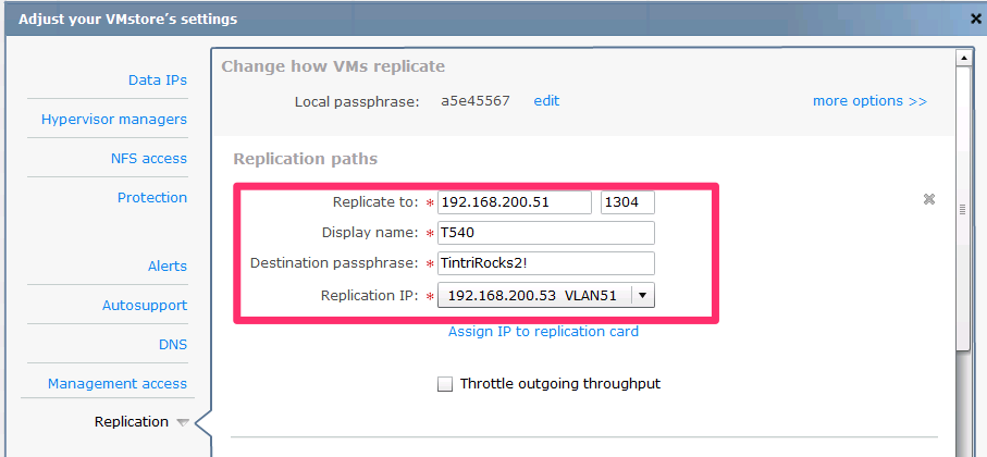
Figure 37. Creating a replication path to the VMstore.
If the “Replication” option is not visible in your Tintri GUI, it is likely that you don’t have a ReplicateVM license installed. If that is the case, please obtain a ReplicateVM license from Tintri, and follow the steps under the “Configuring Licenses” section of the Tintri VMstore System Administration Manual.
Don’t forget to click “Test Paths” before you click Save, as shown in Figure 38.
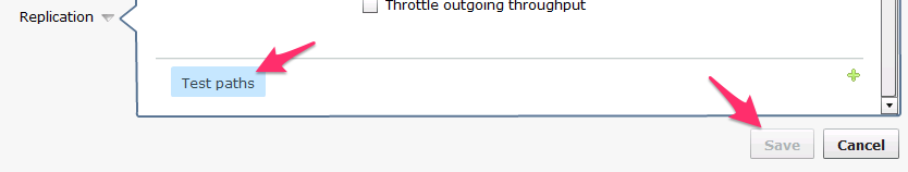
Figure 38. Click “Test Paths” before clicking “Save” here.
Also in the Tintri GUI, create a Service group by going to Virtual Machines/Service groups and clicking “Create group…” Give it a name and select which datastore / mount point you want to protect / replicate.
Note: If the datastore/mount point you just created and moved VMs to doesn’t show up in the dropdown, that means the VMstore hasn’t seen it yet; it can take up to 10 minutes to appear.
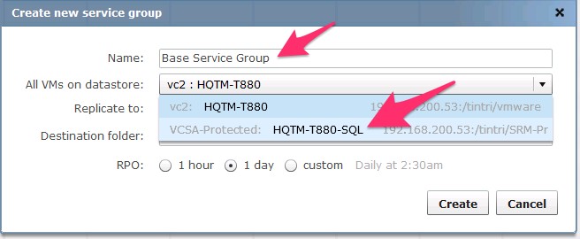
Figure 39. Selecting a replication path for the virtual machine.
Select the right replication path, as shown in Figure 39.
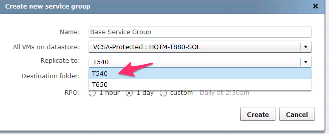
Figure 40. Replicating to multiple service groups.
You can leave the destination folder as the default (“srm”) or change it if you intend to have multiple service groups go into the same VMstore. See Figure 40.
Note: You do not need to create the destination folder yourself; it will be created for you automatically. Furthermore, even if the folder already exists, VMstore will also automatically create a unique name (e.g., srm.1), but still show it as you have input it in this page (e.g., srm).
It’s time to configure the RPO (i.e., how frequently replication occurs, which results in the max age of a recovered VM). With Tintri OS 3.1, the shortest possible RPO is 15 minutes, which can be obtained by selecting a custom interval, then Hourly and then clicking the “minutes past the hour” box, as shown in Figure 41.
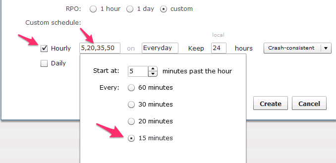
Figure 41. Setting a custom RPO interval.
Configure whether the replicas need to be “Crash-consistent” or “VM-consistent,” as shown in Figure 42.
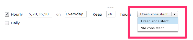
Figure 42. Choosing replication consistency.
The default setting is Crash-consistent, which means that when the VMs come up in the recovery site, they will do so as if the power plug had been pulled out; they will cold boot and check the file system, etc.
You can, however, select “VM-consistent,” which means that before taking a Tintri snapshot for replication, the VM will be quiesced by leveraging VMware Tools and VSS.
The disadvantage of using VM-consistent snapshots in any VMware environment, irrespective of whether a VMstore is being used, is that if the VMs perform heavy IO, VMware’s quiesce process can take minutes and negatively impact the performance of the VM.
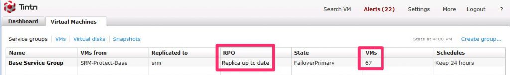
Figure 43. The newly-created service group, showing the number of virtual machines, among other information.
This may be OK if the RPO is long and the snapshots are taken during low-IO periods, but an RPO of 15 minutes may generate frequent snapshots during high-IO periods, resulting in unacceptable performance.
After pressing “Create,” you will see your newly-created service group show up in the GUI, as shown in Figure 43. Note the number of VMs shown and keep an eye on the “RPO;” this will be updated as replication is performed.
The VMstore in the recovery site will automatically be updated with the “other side” of the service group, as you can see in Figure 44. In this example, this will be shown on the recovery VMstore.
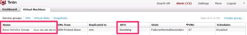
Figure 44. The new service group, with updated information.
Now it’s time to go back to the vSphere Web Client and continue the steps to configure SRM. The next step is to “Add array manager and enable array pair,” as shown in Figure 45. First you are asked if it’s really adding a pair, or only a single one; at this stage, it is the former.
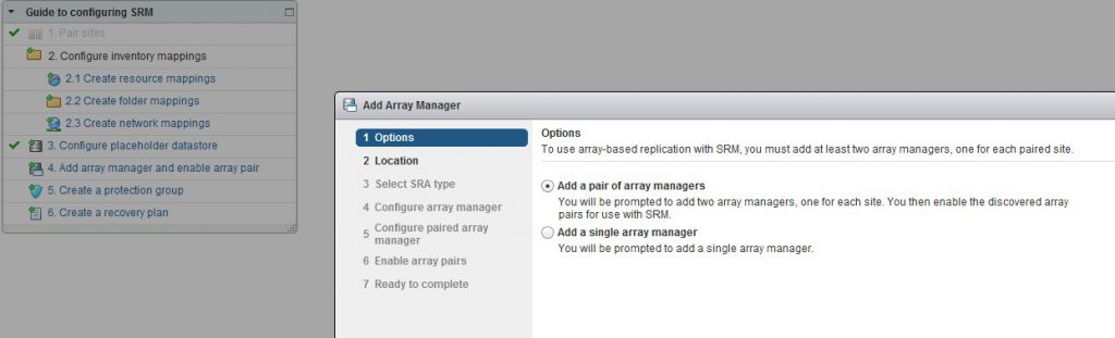
Figure 45. Setting up the pair of array managers.
Pressing Next takes you to the Location dialog (Figure 46), which, since you have already paired the two vSphere servers (sites), should be pre-populated with the right information.
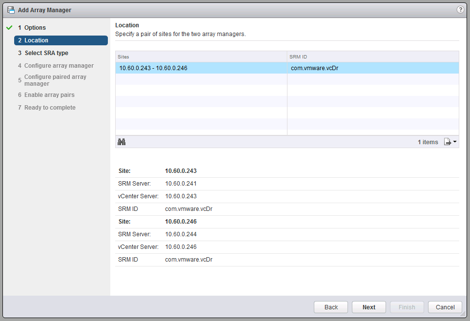
Figure 46. Specifying the location for the array managers.
Next comes selecting the SRA (Figure 47), which, if you installed the SRA in the SRM servers as mentioned earlier, should also be correctly pre-populated.
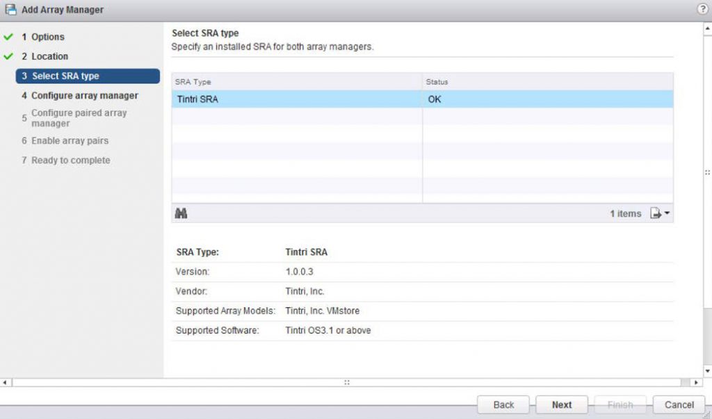
Figure 47. Selecting the SRA type.
After that you will be asked for the VMstore information in the protected site, as shown in Figure 48.
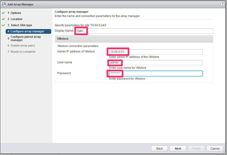
Figure 48. Adding VMstore information.
Note: if you forgot to create a protection group in the VMstore in the “Configure array manager” screen, you will get an error after you click “Next” and will not be able to proceed. If that happens, please go back to Figure 36, “Configure the Tintri VMstores.”
If the protected site’s array manager configuration is successful, it is then time to add the information for the VMstore in the recovery site:
The next screen (Figure 49) is also auto-populated, with the newly discovered array pair.
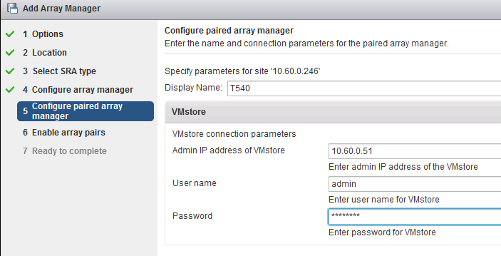
Figure 49. The paired array manager information.
(The array pair that is not selected and says “No peer array pair” shows a replication path that was configured to a different VMstore (i.e., one that is not the one in the recovery site).
Even though that other replication path does show up, because the additional VMstore is not configured in SRM (as it shouldn’t be, since there’s no protection group associated with it), SRM doesn’t see it as an array pair and it can’t be selected.
Figure 50 shows the last step in the array manager creation.
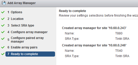
Figure 50. The completed array manager settings.
This is a good point for a quick sanity check.
Go to Site Recovery —> Array Based Replication and select the VMstore in the protected site, then select the “Manage” tab and look under “Array Pairs.”
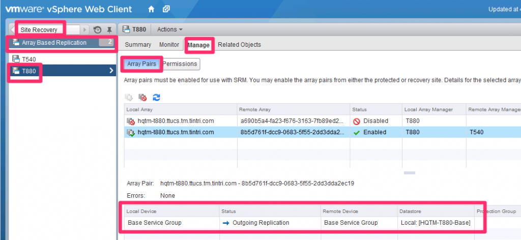
Figure 51. Checking your work.
Select the Array Pair you just created, and you should see (as shown in Figure 51) no errors, and a table containing:
- Local Device. This is the name of the service group created in the Tintri GUI
- This is the “Outgoing Replication.”
- Remote Device. This is also the name of the Service Group you created in the Tintri GUI
- This is the name of the datastore you’re replicating / protecting in the protected site.
If all looks correct, it is time to create a Protection Group.
Give it a name, as shown in Figure 52.
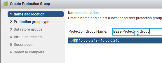
Figure 52. Creating the protection group.
The type should be already correctly selected by default (Figure 53).
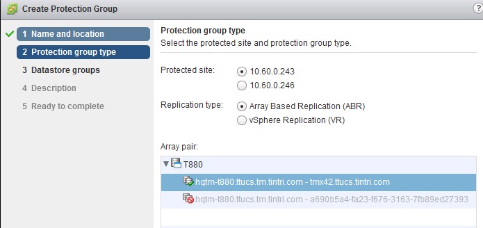
Figure 53. The protection group type is already selected.
You’ll need to correctly select the datastore in the next screen, shown in Figure 54 (make sure you select the one which is already being replicated by the VMstore):
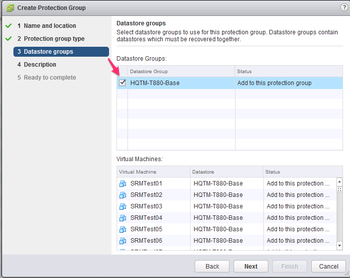
Figure 54. Select the datastore already being replicated.
The VMs residing in that datastore will be automatically selected. There is no way to unselect (unprotect) certain VMs here; that’s why a dedicated datastore was created for them (so that only the ones you want to protect get replicated and protected).
Next comes an optional description. SRM will be working on the VMs for a few minutes to protect them. Once that’s finished, the Protection Status changes to “OK”, as shown in Figure 55.

Figure 55. When you see “Protection Status” set to “OK,” you’re done.
Now it’s time to create the recovery plan, the last configuration step, right before testing SRM.
First, give it a name, as shown in Figure 56.
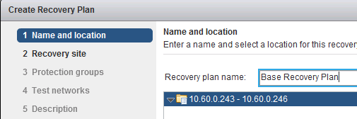
Figure 56. Naming the recovery plan.
Then, select a recovery site (the default should be correct), as seen in Figure 57.
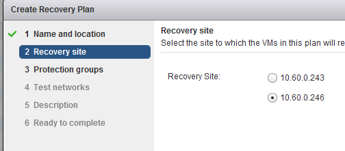
Figure 57. Selecting the recovery site.
Next, the protection group (which you just created), which you can see in Figure 58.
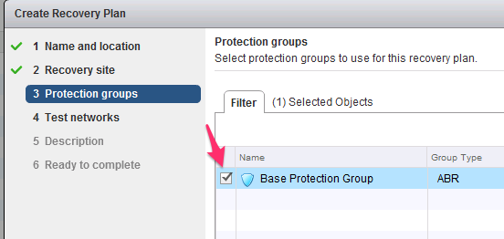
Figure 58. Selecting the protection groups.
Test networks are next (Figure 59). By default, SRM will place each VM in an isolated “bubble” network for a test, and not connect the machines to an actual physical uplink.
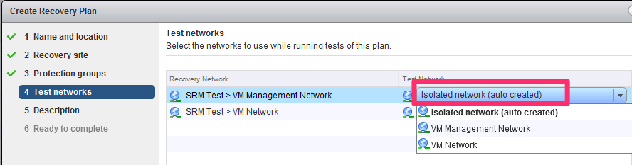
Figure 59. Select the test networks for the recovery plan.
Then there’s an optional description, and that’s it.
Recovery plans are ready immediately after creation, as shown in Figure 60.

Figure 60. The completed, ready-to-go recovery plan.
Previous sections showed the entire configuration needed. Now it’s time to do a test recovery plan.
As explained earlier, a recovery plan doesn’t actually fail over the VMs to the recovery site; it synchronizes the replica VMs and then enables (powers up) the VMs in the recovery site, in a test (isolated) network. That shows the replica VMs are OK and working.
What it doesn’t do is disable the VMs in the protected site and yield full control to the VMs in the recovery site. Yielding full control would mean that the recovery site VMs would now be the primaries, be connected to the production network and be the authoritative copy.
In a test run, the protected site still has the authoritative copy of the VMs, and when the test ends and SRM cleans up, it simply shuts down the recovery VMs and overwrites them with a new replica from the protected site.
In an actual failover/failback scenario (as we’ll see), the VMs in the recovery site have to be replicated back to the protected site before they are brought up.
A typical test recovery plan is shown in Figure 61.
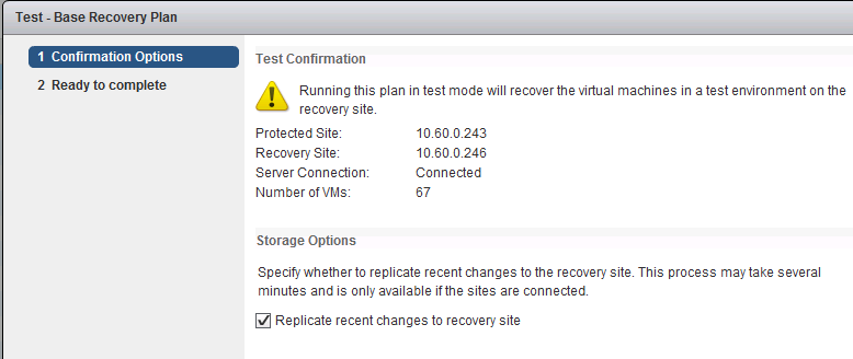
Figure 61. Confirm the test plan options here.
The Monitor tab (Figure 62) will show you what’s going on as it happens.

Figure 62. The “Monitor” tab updates the test’s progress.
Figure 63 shows the screen after a successful test; note how blazingly fast the replication happens; there are 67 live VMs that get replicated in about a minute by the VMstore. This is made possible because the VMstore replicates only changed blocks after deduplication and compression.
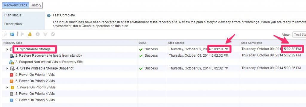
Figure 63. Note how quickly all 67 virtual machines have been replicated by the VMstore.
Figure 64, from the Tintri GUI, also shows how little impact the replication process has had on the protected VMstore, even if it’s set to replicate every 15 minutes and there are 67 extremely active VMs.
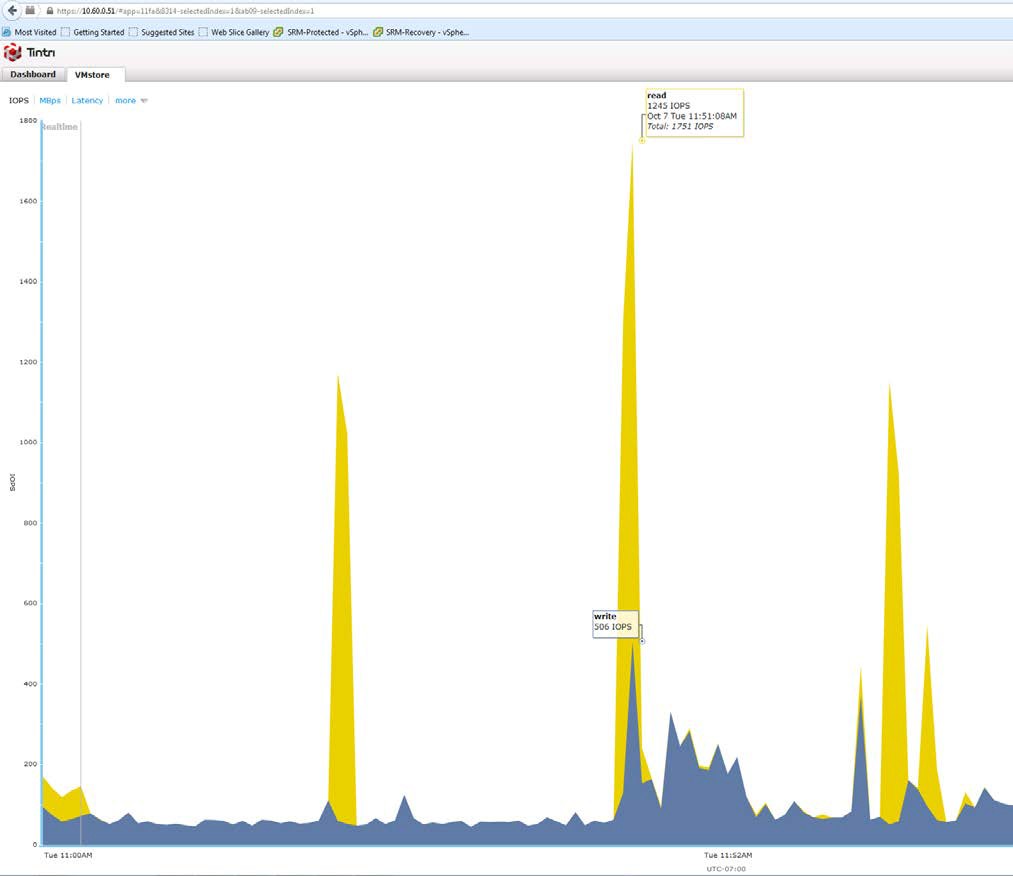
Figure 64. Replication doesn’t impact VMstore very much.
After a test, don’t forget to press the Cleanup button (Figure 65), or DR won’t work correctly. A cleanup, among other things, removes the test network from the recovery site.

Figure 65. Beginning the important cleanup phase.
A recovery plan should only be actually run if there’s some kind of event at the primary (protected) site that mandates it. A recovery plan should not be run for testing purposes; that’s what the Test feature (described in the previous section) is for.
If you do run a recovery plan, the recovery site will completely take over and the VMs in the protected site will be taken down.
Even if there’s an actual DR situation (the protected site goes down hard), you will still need to run the recovery plan as soon as you get the chance. This is because the recovery plan process does a lot of housekeeping items that don’t necessarily get performed automatically if the protected site goes down.
The only difference is that when you run the recovery plan in a DR situation (rather than a planned migration), you select a different option when you trigger it, as shown in Figure 66.
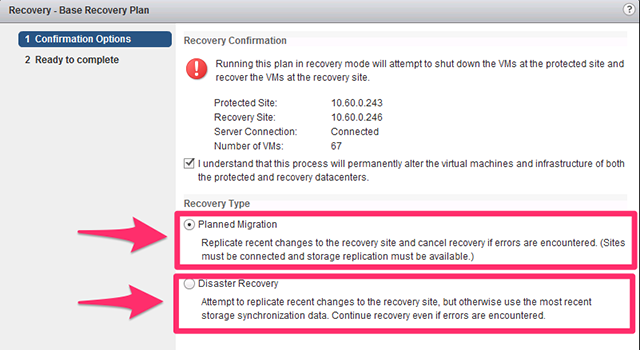
Figure 66. Make sure to check the proper recovery type.
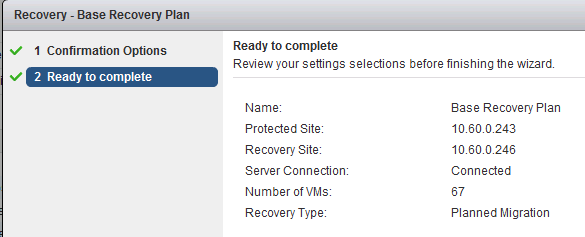
Figure 67. Confirm the recovery plan for Site Recovery Manager.
SRM needs confirmation before proceeding, as seen in Figure 67.
(DR and planned migrations were tested in writing this document.)
In the DR case, the recovery site was running recovered VMs in fewer than two minutes after the plug was pulled on the protected site.
The whole recovery plan process (including housekeeping) took about four minutes in both cases.
After a recovery plan has completed (successfully), the failback to the protected site is performed by clicking the “Reprotect” button, shown in Figure 68.

Figure 68. Failback to the protected site.
With SRM and Tintri, pressing the button will perform the reversal fully automatically; the replication will automatically be reversed, as shown in the vSphere Web Client (Figure 69).
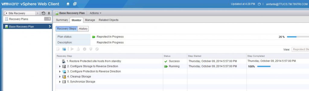
Figure 69. The vSphere view of the completed recovery.
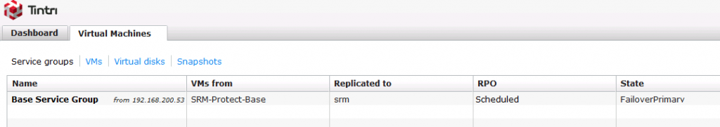
Figure 70. The Tintri view of the same recovery.
It will also be shown in the Tintri GUI; Figure 70 shows what the recovery site VMstore looks like (note the “State” shows “FailoverPrimary”). The protected site VMstore in Figure 71 shows a state of “FailoverFormerPrimaryExpectingReverse”.
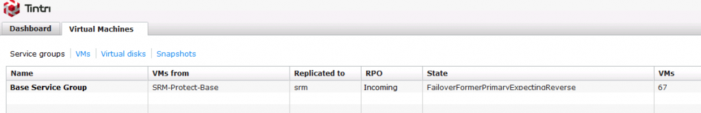
Figure 71. The protected site VMstore, with the updated State.
Tintri VMstore was designed from the ground up for virtualization and cloud workloads, and purpose-built to take full advantage of flash technology.
Tintri’s legendary ease of use and low TCO now extends to VMware SRM, too: you can have your SRM- based DR environment up and running in mere minutes, with low maintenance and an unbeatably low TCO.